Deliver to Peru
IFor best experience Get the App


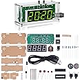
MiOYOOW Soldering Practice Kit, TT Motor Line Following Robot Car Kit Beginners DIY Smart Car Solder Project Kit for School STEM Education, Learning Electronic Toys for 10+ Years Old Boys Girls


Description
🤖 Build, Learn, and Play: Your STEM Adventure Awaits!
- 🧠 BUILD LEARN - Master soldering and electronic skills with ease.
- 📚 GUIDED LEARNING - Includes an English manual and QR code for easy access to instructions.
- 🎨 DESIGN YOUR PATH - Create custom runways for endless fun and creativity.
- 🚀 IGNITE CURIOSITY - Perfect for STEM education and hands-on learning!
- 🤖 SMART TRACKING TECH - Utilizes photoresistance for autonomous navigation along black lines.
The MiOYOOW Soldering Practice Kit is an engaging DIY smart car project designed for students aged 10 and up. This kit teaches essential skills in soldering, electronics, and mechanical structures while allowing users to create custom runways for their robot car. With clear instructions and easy assembly, it's perfect for beginners and promotes valuable STEM education.
Specifications
| Supported Battery Types | Alkaline |
| Theme | Physics |
| Item Dimensions | 4 x 2.8 x 0.06 inches |
Have a Question? See What Others Asked
Reviews
B**N
Cool
Easy to do, even a six years old could do this under parental supervision.
G**Y
Fairly easy and fun when done
Remote control version. Download pdf instructions. 11yr old did this with guidance. Fairly straightforward. Only issue was wires to board. They go to pads not through holes so a bit mor tricky to solder. Just put a bit of solder on pad then come back and solder wire. He enjoyed running the car around with the remote.
L**Y
Easy stem project
Enjoyed this project so much! All components as listed. My wheels were not so sturdy not sure if it was a me thing or not.
K**K
Awsome
This is another one of those amazing soldering projects for people learning to solder that is also great if you're trying to teach your kids how to solder. Because when you get done you don't just have something that you put together and you can turn a light on but you've actually made something that's a toy that your kid probably would have begged you to buy in the store pre-assembled. I would say the value of these is definitely worth it, the assembly isn't the easiest, but it's not supposed to be. But once you get them put together they look great and as long as you've done everything right they work great. They come with a little piece of paper that has a black loop on it that they will follow but you can take black electrical tape and put it on your floor in any pattern you want and they will just follow around the pattern. My daughter and I set up a racetrack with two strips and unfortunately hers always seems to beat mine for some reason. But it's been a great product a lot of fun to make and a lot of fun to use after
A**V
This thing drove me nuts, but is now working really well.
TL;DR; Use good batteriesAssembly problems: The instructions are really lacking. It's so strange that they completely omit the motor connection step. The polarity of the motor pads on the PCB is not marked. I've soldered the motors exactly like in the picture in PDF and they were both backwards. If I remember correctly, you need to solder the motor connector which is closest to PCB to the pad which is closer to the back of the car.Soldering photo-diodes and white LEDs was tricky without another hand.After my son and me finished soldering and assembling, I quickly tuned the car using potentiometers and it ran perfectly the first time.But it only ran once!I wanted to calibrate it a bit more and one side stopped responding (the motor was always running). I could never get it back to working state.Next day I've spent several hour with multimeter. I managed to make both sides of the car to react to bright light, but it did not work with it's own lights.With bright light, the inputs were ~400mV and the LM393 chip compared them correctly, outputting ~2V from one of the outputs.With car's own lights (+white paper) however the inputs were ~1.4V and both outputs were always <0.1V regardless of which input was higher, so both wheels were always spinning. The potentiometers were not helping much - AFAIR, they changed the inputs in the 1.3V-1.5V range.I've started reading about the problems with the LM393 chip and found one forum page that said that the inputs need to be ~1.2V lower than the chip VCC for the chip to work. This was definitely not true for me, since the chip was only getting 2.0-2.4V which is closer to the input values.I've replaced the batteries (strange - the ones I've used were pretty new) and the car started working again!So, 5 stars for my education. 1-2 stars for instructions.Feature requests:* Definitely fix the instructions regarding the motor soldering and installation.* Repurpose potentiometers, so that one of them sets the base level and the second one sets balance. It will make calibration easier. The "base" potentiometer should probably have bigger range, so that it can cover more situations.
D**N
A Lot of Fun
This kit was fun to build and a lot of fun to watch it follow a line with blinking red LEDs (red lens) on top. When it runs, two red LEDs (clear lens) illuminates the line it follows. The two LEDs on top are used with the trimmer potentiometers for tuning when the left/right motors turn on so it can follow the track (line).I took a bold felt pen and drew an oval around a single piece of printer paper. I did not expect it to follow turns that sharp, but it worked. Line width may have been about 1/2 inch.You will need to have a soldering iron and solder and a way to remove a small amount of insulation.I used the battery pack to compare the two leads on the motors and connected the motors the right way on the first try. If the motor goes the wrong way, just reverse the wires. My kit had 'five-band resistors. Resistor value color codes can be found on the internet. The manual was great about warning IC’s are polarity sensitive. The board was well marked for other polarity-sensitive parts.This was pretty fun. It makes me wonder if someday model train track will be printed at home.
B**N
Junk ewaste kit
Don't bother with this, it's junk. It works sort of, but it's silly to assemble, included no basic helpers like stand offs for the leds and sensors. Only provided about 5 minutes of entertainment for my kid before it became annoying to try to adjust to actually follow a line around turns, etc. Save yourself the ewaste and pass. There are better robots out there with the same principles.
R**B
Challenging but works - No manual seems to be available
I found no manual or QR code in any of the product images.They have some tips in the description but this is a non-trivial project. Had looked at purchasing for a camp with 20 kids with 90min slot to build. It took me over an hour to build as an expert (taking some photos) so it would be over 2 hrs with a assistant and a novice, Still a very cool project if you have time and an assistant to help.Biggest problem I saw was the complete lack of clarity on polarity of motor. I had to tin leads and touch to board to find correct writing to cause vehicle to move forward. Hint is the top lead (when motor mounted goes to the forward pad on the board for both left & right motors.Also because they do not want to spend another 2 cents on foam. Both the chip & socket have their leads mangled in shipping and must be carefully straightened before assembly.
Common Questions
Trustpilot
1 day ago
1 month ago
Get the App
