


🔍 Discover the unseen with the ultimate DIY Geiger Counter!
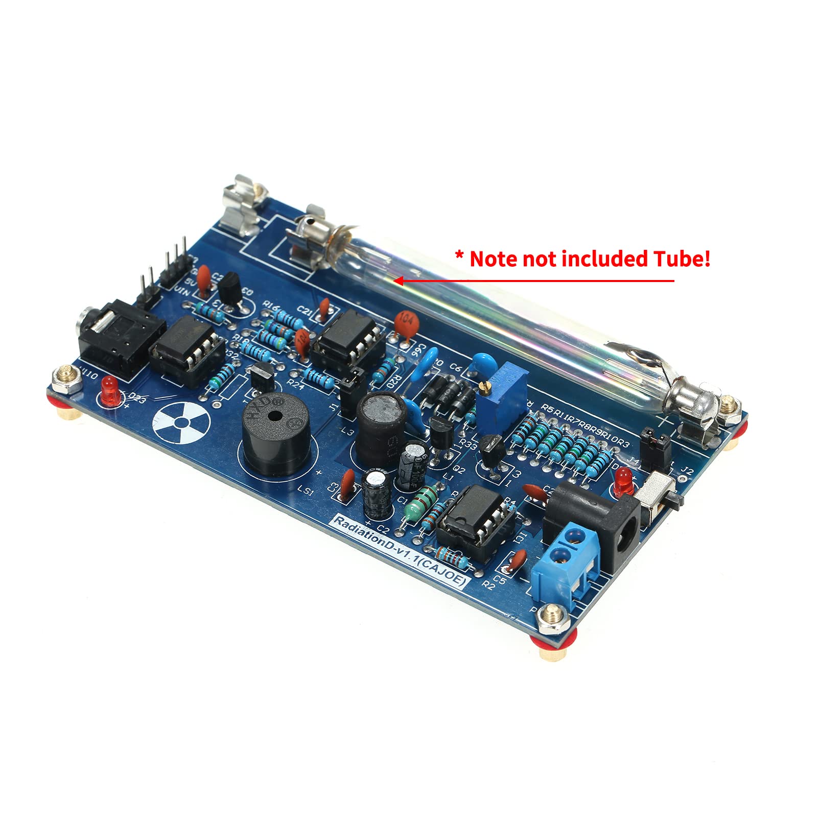
The Assembled Radiation Detector System is a versatile DIY kit designed for radiation detection enthusiasts. Compatible with Arduino and various Geiger tubes, it supports a voltage range of 330-600V. This durable kit allows for PC data acquisition and Matlab analysis, making it an excellent choice for software developers and hobbyists alike.
| Graphics Card Interface | PCI Express |
| System Bus Standard Supported | SATA 3 |
| Total SATA Ports | 4 |
| Platform | iOS |
| Compatible Devices | Personal Computer |
| Item Dimensions L x W x H | 7.48"L x 5.12"W x 2.76"H |
M**K
An excellent experimenters board
Likes:High quality PC board materialComes with everything that most people might need to get startedThe board is designed with experimenters in mindThe board is easily interfaced with external devicesAll of the IC's are in socketsDislikes:no documentation included(but a simple web search will find it online)
H**A
works well
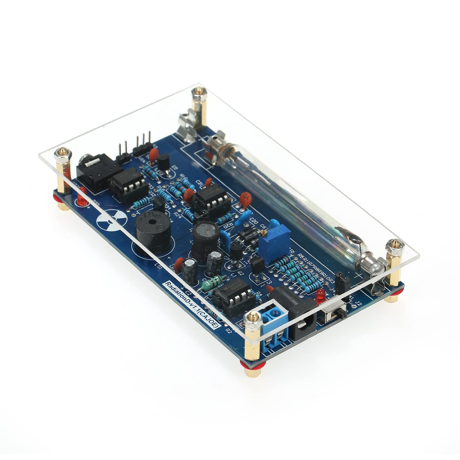
It works well but the acrylic shield mounting holes do not line up with board holes. There is no information for the connectors on the board. The power connectors were obvious as was the audio output connector. How ever, there are others for which an explanation would be helpful. What is the purpose of the 3-pin connector labeled. P3 ; GND, 5V, Vin. 2 pin connector J4 labeled 'test', and J2 with no label and P100 with a jumper.The small red LED could be much brighter. The sounder is very good.It does work well., and the battery holder is good. It can be powered with a USB port (Cable included) and a 3mm audio cable is also included. There is also a 3-wire cable. that will permit connections to an Arduino but with instruction as to how to do that.I have no idea how to determine accuracy, so I just gave 3 stars.This is well made and inexpensive but the lack of hook up information is not good. This may be useful as is for many. It does in fact detect radiation so I can recommend this for the hobbyist. It would be fun to hook it up to an Arduino if you can figure it out.
M**L
Horrible quality and apparently used
I ordered 12. All of them ha cold solder joints. The soldering looked like it was done by someone who did not know how to solder. There were wires sticking off the board that were not supposed to be there and they were clipped off with stubs. These wires were like that on 8 out of 12 boards. The extra wire stubs were connected to the 350 volt power supply.To qupte Joe Biden: "One word: Do Not Buy."
M**T
Muon Coincidence Detector
I bought two of these, two tubes and a 74HC08 ($2) AND-gate microchip to detect muons.DIY Muon DetectorMuons are fundamental particles created when cosmic rays collide with particles in Earth’s atmosphere. They are way more powerful than x-rays—but can be used in similar ways to CT Scan devices; but with larger/thicker objects. Instead of CT Scanning someone’s body, you can use the stronger muons to image entire Egyptian/Mexican pyramids and find hidden, undiscovered rooms. Likewise, instead of just x-raying a suitcase at an airport—you can scan an entire plane’s cargo hold. Its first real-world use was in 1970 when scanning the Pyramid of Khafre, looking for hidden rooms.So, of course I want to try detecting a muon. Not a whole bunch—just one. Reliably.How do scientists detect muons? They can follow the tracks in a spark chamber (which I have, but it’s too small). They can use photographic film—I have a darkroom. They can use scintillation crystal sensors—which I have, but I don’t have dozens of them.How will I detect muons? By using the humble Geiger counter with a Geiger-Muller tube. A Geiger counter is basically a lightbulb with a tiny gap in it filled with gas. When a particle passes through the lightbulb (tube) it completes an electrical circuit and you get a click noise.Basically Geiger-Muller tubes are just like those bug zapper lights people have in their backyards.I'm using the humble Soviet era, 400 volt SBM-20 tube for this. Two of them.But Geiger counters will click when hit by X-rays, gamma rays, alpha particles, beta particles, etc. Plus all the background radiation makes them click around 20 times a minute in a normal room.So, we cover the Geiger-Muller tube in a lead sheet, which will block most of those particles.Then we get a second Geiger-Muller tube and cover that with lead.Then, and here is the genius part, we stack the tubes on top of each other so that the only particles/rays that would trigger both tubes would have to be: traveling at 90 degrees to the Earth’s surface; be powerful enough to pass through not one, but two sheets of lead and two tubes; and be moving so fast as to trigger both tubes virtually at the same time via relativistic motion.How do we know if the tubes are triggered at the same time (not just close)? With a humble AND-gate microchip. This microchip has two inputs and one output. Only if it receives two input signals at the same time will it output its own triggered signal (and light an LED or make a click on a speaker or a spike on my oscilloscope).If you look at the pinout of the chip (a 74HC08 AND gate logic chip) you will see that if PIN1 and PIN2 get a signal at the same exact time = it will output a signal to PIN3.Pin1 and Pin2 also each get a 100k resistor to ground (this lets the chip reset to off).The yellow wires are input Pins 1 and 2. They have 100k resistors going to negative rail.The other end of the yellow wires go to the 3rd pin of the NE555 chips on the geiger boards. One yellow goes to one pin3 of geiger board, the other yellow wire goes to pin3 of the other NE555 chip on the other board.Here are the yellow wires going to Pins 1 and 2 on the 74HC08 chip. Notice the 100k resistors going from each one to the (blue) negative rail on the breadboard.Here is the other end going to Pin3 of the NE555 chip. According to the schematics it should be possible to tie into this via a jumper or LED or speaker connection of the geigers, but that doesn't to work.Thus, this is what's known as a coincidence detector.So, stack two cheap Geiger counters sandwiched in lead plates.Output from both go to a $2 logic AND-gate chip.AND-gate chip outputs to: LED or Oscilloscope or Speaker.Literal back of an envelope layout:Any output basically must equal a muon. They occur about once per minute on Earth.To make things easier I connected one geiger board to a 5v USB wall plug that had a higher (2 amp) current rating than usual. Not sure this is necessary.Then I connected the always on screw tightening power block things together from both units. That poweeed the other board.Then I ran a second pair of power wires to the breadboard.So, USB wall plug to first geiger board. Then red and black wires between the boards:Then another pair of red and black split off to power the breadboard:Those go to the red and blue power rails on the breadboard. I also ran a short black wire from the right blue negative to the left vlue negative rail on the breadboard. That way I could easily run 100k resistors from the 74HC08 1 &2 Pins to the negative easily.I'll probably reroute that more cleanly in the future. It was a quick test. My breadboard LED came on with mo input! That's why the resistors are needed to zero everything out and start with an OFF LED. Weird, but thats how logic chips like the AND gate work. You have to tell them what 0 or off looks like or else they go nuts.So, it works.If I test by turning both on I get an occasional light up by the LED on the breadboard. Especially if I put a radioactive substance near them. Even then, it doesn't light up often relative to the individual Geiger counters clicking and blinking. Good!In the future I might pull each Geihlger board's J1 jumper to disable their speakers--and then put a speaker on thr breadboard.Took less than an hour!M1K3 FROM D3TR01T
C**O
Decent For the Price / Took Some Serious Rework
I bought this a few years ago, but was somewhat disappointed by the build quality. Lots of cold solder joints and two bridged traces. Back of the board had about half a pound of crystalized flux residue still on it.I'd bought it to play with an LND712, but there was no way i was going to risk my brand new expensive tube on something that I had no faith could maintain the proper HV level without shorting out. Put it in a box and forgot about it.Off work for a few days for some medical issues and finally had time to properly bathe the board in alcohol, rework the problem solders, and run some tests. Five hours later, and its sitting on my desk ticking away happily. Was the low price necessarily worth my time on a normal day? Probably not. But since I was bored, I'm glad I had a project.
Z**T
It works
It was assembled well enough, minus some shifted components here an there. If you get the soviet tube, you have to bend the inner tab out to allow it to connect to the two furthest clamps. The enclosure seems as though it was lifted from another project and just slapped in with this board. It does not fit so you have to do a bit of finagling to get it assembled.
S**R
Not a complete kit. Tube and other items not include.
This is not assembled. The only thing that is assembled is the circuit board. A Geiger tube and other components are not included. There are not any instructions or diagrams. The box contains the circuit board and these loose items: battery holder, 4 standoffs, Plexiglass front, short USB-A male to coaxial cable, and a short pin header connection cable. If that's all you need, so be it. I was expecting everything needed and to just connect everything and start using it. I was disappointed. You will probably spend more than the cost of this module to create a working Geiger counter.
Trustpilot
2 weeks ago
1 week ago
