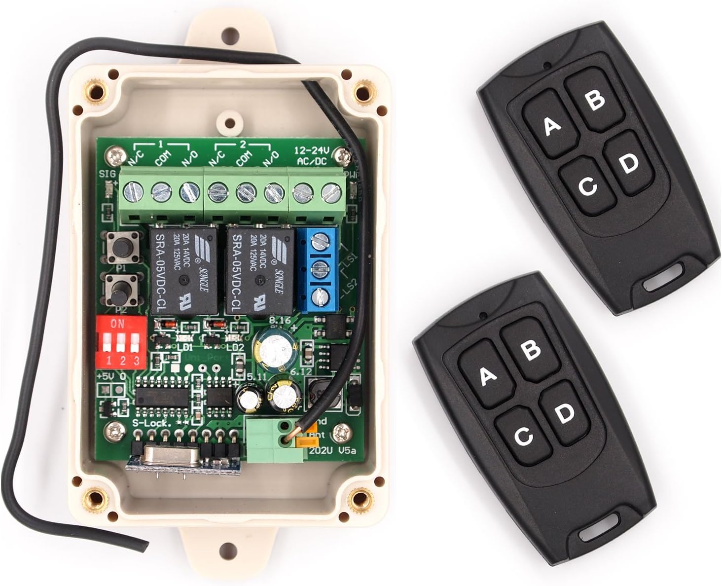
🔑 Unlock the Future of Control!
The Solidremote 12V - 24V Secure Wireless RF Remote Control Relay Switch is a versatile and secure solution for controlling various electronic devices. With a robust design that supports dual-channel operation, it offers unmatched security with over 18 quintillion code combinations. Its weatherproof enclosure and easy installation make it perfect for both indoor and outdoor applications, while its powerful performance allows for reliable control of up to 10A.
Connector Type | 3-pin Terminal Block Connector |
Contact Material | Steel |
Contact Type | Electrical |
Current Rating | 10 Amps |
Mounting Type | Wall Mount |
Brand | Solidremote |
Operation Mode | Automatic |
Wattage | 1.2E+2 |
Coil Voltage | 12 Volts |
Contact Current Rating | 10 Amps |
Maximum Switching Voltage | 24 Volts |
Minimum Switching Voltage | 12 Volts (DC) |
Number of Terminals | 3 |
UPC | 708296998994 |
Manufacturer | Solidremote Technologies Ltd |
Part Number | KIT-1 |
Item Weight | 5.3 ounces |
Product Dimensions | 4.72 x 2.83 x 2.16 inches |
Country of Origin | China |
Item model number | SR-RCS-202U |
Batteries | 1 Lithium Metal batteries required. (included) |
Is Discontinued By Manufacturer | No |
Color | Black |
Finish | Mixed |
Material | Case is plastic |
Pattern | Modern |
Power Source | 9-30v Dc Or 9-24v Ac |
Amperage Capacity | 10 Amps |
Installation Method | Optional installation using mounting holes |
Item Package Quantity | 1 |
Number Of Pieces | 1 |
Switch Type | 2 relays with NO NC and COM terminals available |
Usage | Indoor and outdoor use |
Included Components | 1 x 202U receiver + 2 x TX134 remotes + 1 x instruction sheet |
Batteries Included? | Yes |
Batteries Required? | Yes |
Battery Cell Type | Lithium Manganese Dioxide |
Description Pile | CR2032 |
Average Battery Life | 2 years |
S**R
Simple but effective
I have purchased a v5, a v6 and now a pair of extra remotes. The v6 has not been installed yet so my comments are regarding v5 only w the newer remotes.One of the original v5 remotes was crushed by traffic so I purchased the v6 with the intent of using the remotes w the v5 unit and keeping the v6 unit as a backup. I then decided I would use v6 in another project so bought a pack of the spares anyway. But before the spares arrived I had already programmed the v6 remoted to my v5 and they are working fine. (More on that below.)I'm pretty sure I have an older review on the v5 so I'll just throw a few points out here. First, i have it installed inside an aluminum trailer (to turn on interior and exterior lights A=interior B= Exterior C= Both) but it still has pretty good range and reception. Batteries last a long time. Set up, even utilizing relays to handle more amperage, was very simple. This has been working flawlessly since 2019 (now Q2 2024).PROGRAMMING NEW REMOTES - I don't recall having any issues programming the original remotes, and I'm betting that would be true of the new v6 unit, however linking newer remotes to the older units may require changing the remotes 'mode'. This is not stated very clearly, if at all, in most documentation or videos. I don't have all of the details but here's the basic idea. When you press one of the buttons on an original remote does it blink once and go out, stay on for a longer moment, or blink several times? This is an indication of its 'mode'. When you get new remotes the mode is likely set to the default mode at the time of its fabrication, thus different from an older model, and you probably see the new remotes flash differently from your old remotes. You need to get the new one to match the old one. To change the mode you hold the C+D buttons at the same time until you see the remotes light come on/flash, let go of C+D and press A. You should now see a different pattern when you press a button on that remote. If you are 'lucky' that's the one that matches your base unit so you should try to pair them again following the documented (simple) process. If the unit and remote didn't pair up then try changing the remotes mode again. I had to change the modes many times before they finally linked up. Not sure if it makes a difference but I also tried pressing the B and C buttons (after C+D) in case that did anything special since the C+D> A just plain didn't work after the first few tries. It can be frustrating but after a couple minutes of feeling like I was getting nowhere it eventually worked.Overall a great product!UPDATE June 2024 - I ended up adding the additional standalone remotes to the same v5 controller and found that they were already in the correct 'mode', unlike the remotes that came with the newer v6 unit (described above). This is neither a plus nor a minus since it just depends on your situation as to whether you'll need to adjust the modes or not for pairing. If i had wanted to pair them with the newer v6 unit then I'd likely have needed to change the mode.
M**N
Excellent product, easy installation
I am extremely happy with the Solidremote Receiver and ease of installation. I still can't believe what a simple, inexpensive and easy solution this is for my needs.I had been searching for a way to add a remote capability to a garage screen which could only be opened by a single button/switch, making it very inconvenient when coming home in the car and with the screen down. I saw several reviews here and a U Tube video and bought the Solidremote receiver unit (Receiver), a 12-24v AC/DC adapter to plug into an outlet to power the Receiver (I bought mine on Amazon), a length of doorbell wire (or similar gauge), 2 strand, (if only 3 strand available cut off 3d (usually green) wire) to splice into the existing switch and connect to the Receiver, and 2 extra remotes .The directions provided are essentially useless for installation and wire hook-up. If you have done any electrical work such as adding, changing outlets, switches, etc., an absolute breeze to install-I don't know about 5 minutes as another reviewer suggests, but very simple. Even without much experience, installation is still easy. All you are doing is splicing into your existing 12 v switch for your device and using the adapter to power the Receiver, so there is no running 110 wire or anything like that.My comments relate ONLY to installing the Receiver to switch 1 device- this Receiver has several other uses.You need to figure where you will install the Receiver, accounting for access to the existing switch for your device to install a length of the bell wire from the switch to the Receiver, and a 110 outlet to plug the 12/24 v adapter from the Receiver into. Do the wiring before you screw the Receiver to the wall/device. As you look at the Receiver, remove the cover, orient the Receiver to put the Terminal Block (light green), on the bottom-on the right of the Terminal Block are #1 and #2 relays, I used the #1 'relay' (R1) since I had only the one garage screen I wanted to switch-I suggest you do the wiring before you screw the Receiver down. Take your length of bell wire, strip off 1/4-1/2 inch of each wire and install one each in to the COM and NO terminals at R1, on the far right as you look at the Terminal Block, through the right hole in the "bottom" of the Receiver-polarity (color of wire) doesn't matter. Then go to far left of the Block, look for the last 2 terminals under the designation on the Block 12-24V AC DC, which is the power part of the Terminal you will hook up to your 12/24 v adapter. Depending on your model adapter, it may already have a terminal end you can use by adding a length of the bell wire, otherwise cut the end plug off, strip the wire exposing 2 wires, strip as necessary and install into each of the 2 terminals under 12-24V AC DC designation on the Block, through the left hole on the 'bottom' of the Receiver-polarity (color) of wires doesn't matter. NOTE: Also on the Receiver there is a red block with 3 or 4 switches -totally ignore, leave as is. There is also a blue block with 3 terminals, ignore, do not use.You are ready to splice into your existing switch. Go to your in use switch for your device, take off the cover if any, note the 2 terminals on the switch; strip off the other end from the wire you installed at R1 on the Receiver, exposing the other ends of the 2 wires and combine one each existing wire on the switch with one each of the wires from the NO & COM terminals on the Receiver, on each of the terminals of the existing switch-polarity of the wires you respectively install on the existing switch terminal doesn't matter. Plug the adapter into the outlet, on the circuit board of the Receiver should see some small LED lights.The directions supplied do a good job explaining how to program the new remote(s)-I suggest you use PRG 1 to program your remote(s). I also put a mark on the Receiver at PRG 1 as a guide for future re-programming. Be sure and test the remote(s) after programming.There also is a very narrow piece of white tubing as a gasket for the receiver if installed in a wet area-I didn't use.Once the remote(s) programming is done and tested, you can then reinstall the existing switch (which will still work independent of the remote(s), and install the receiver on a solid surface. Enjoy!
Trustpilot
1 week ago
4 days ago